
 Home /
Mechanical Part Design for Injection Molding: Engineering Rules for Reliable Mass Production


Creating functional CAD geometry is only part of designing mechanical parts for injection molding. There are numerous factors that are critical for optimal design for dimensional stability and control for consistent production.
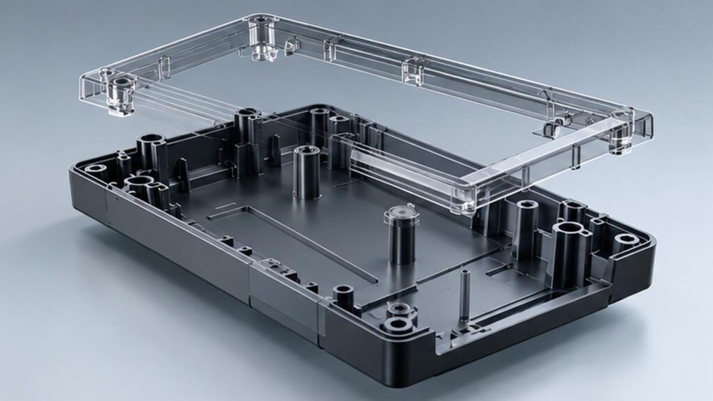
Our approach at LKK Design incorporates mechanical design, design for manufacturing (DFM) and tooling feasibility to analyze the risks and provide better design solutions for an injection molded part prior to mold fabrication.
1. Key Engineering Principles for Injection-Molded Parts
There are key principles of mechanics that are important to understand in injection molding. The first of which is the behavior of part geometry during the filling, packing, cooling and ejection process of the mold.
Wall Thickness, Draft Angles and Structural Features
| Feature | Engineering Guidelines | Manufacturing Impact |
| Wall Thickness | Nominal thickness uniform throughout; gradual thickness transitions | Less differential shrinkage; less warpage |
| Draft Angles | Start around 1-2 degrees and adjust for depth and surface texture | Less ejection force and surface damage |
| Reinforcing Ribs | 40-60% of nominal wall thickness | More part stiffness with less material build up |
| Screw Bosses | Rework design to use cored sections and ribs to support loads | Size for fastener |
| Corner Radii | Avoid sharp | Internal corners and make smooth transitions |
Injection molding is relatively complex, and geometry differs based on what resin is used, how far the material needs to flow, the surface requirements of the part, and the capabilities of the tooling. These are general guidelines.
Designing Functional Connections
Some snap-fit connections require consideration of cantilever lengths, insertion force, maximum strain, and the repeated nature of the assembly.
Other considerations for screw connections include:
• Screw engagement depth and boss hoop stress.
• Use of threaded inserts versus thread forming screws.
• Local cracking due to installation torque.
• Creep of the material under load.
• Boss thickness may be increased to decrease hoop stress, but may also increase sink.
2. Selection of Material and Effect of Dimensional Stability
The selection of the right material for a part influences the behavior of the part during molding as well as the type of loads, exposure to temperature and chemicals, and the requirements for assembly.
| Material | Typical Applications | Critical Engineering Considerations |
| ABS | Electronic housings, structural covers | Impact resistance, dimensional stability, chemical exposure |
| PP | Living hinges, lightweight components | Shrinkage, lower stiffness, long-term creep |
| PC | Impact-resistant enclosures | Residual stress, environmental stress cracking |
| PA / Glass-Filled PA | Load-bearing components | Moisture absorption, fiber orientation, anisotropic shrinkage |
Shrinkage and Tolerance Control
Thermoplastic shrinkage is affected by material grade, mold temperature, packing conditions, and part geometry.
Glass-filled polymers can exhibit shrinkage in different directions, i.e. shrinkage can be different parallel and perpendicular to the direction of the melt flow. This can cause distortion of flat surfaces and/or can move hole positions.
Tolerance design requires the following:
• Establish functional datums and critically mating dimensions.
• Apply GD&T to location and form features and/or assembly-critical features.
• Recognize general molding tolerances and critically fit tolerances.
• Confirm dimensions considering prescribed temperature and conditioning requirements.
• ISO 20457:2026 is a reference document for plastic molded-part tolerances and acceptance conditions.
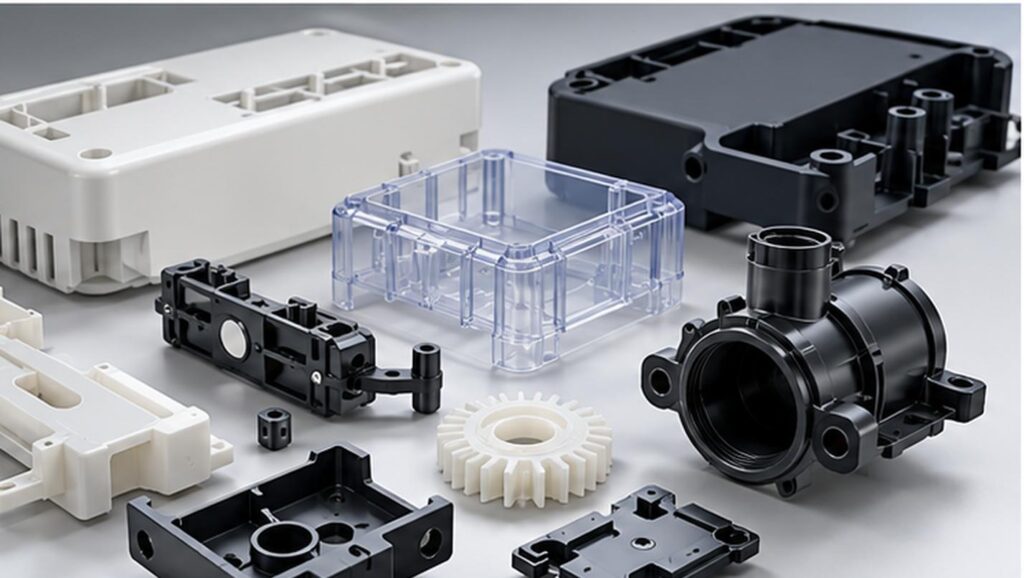
3. How Mold Design Constraints Affect Part Geometry
Part design constraints due to the need to allow for mold opening and material flow can significantly impact part cost and complexity.
Parting lines, Undercuts and Gate Locations
• Four design issues are considered during a DFM review:
• Parting line location, which can impact flash and/or dimension consistency.
• Undercuts, which require sliders or lifters, or, if possible, straight pull molding.
Side Action Requirements
• Gate Locations: Determines melt-flow direction, packing effectiveness, and potential weld line locations.
• Ejector Locations: Must release thin walls, bosses and cosmetic surfaces without splitting.
• Weld lines require extra attention where they intersect loaded snap-fits and other stressed features.
There are locations where gate placement and fiber orientation can effect local part strength of joined injection molded parts.
4. DFM Analysis: Preventing Defects Before Tooling
A sound knowledge of Mechanical Design for Injection Molding should be confirmed through an engineering analysis as opposed to a simple CAD check.
Some of the Defects Found in Injection Molding
| Defect | Causes | Response |
| Sink Marks | Insufficient packing | Analyze ribs, cores, and packs |
| Warpage | Anisotropic shrinkage | Study wall thickness, cooling, and flow |
| Short Shots | Inadequate flow | Correct flow length, wall thickness, and gate |
| Weld Lines | Melt fronts | Gate strategy, local strength |
| Ejection Damage | Insufficient draft, release, and ejection | Change release and ejector geometry |
Verification from Prototype to Production
Verification at LKK Design revolves around consideration of design for manufacturing (DFM) at the mechanical design stage.
Activities for the verification plan will consist of the following:
• Review CAD’s and DFMs to verify critical dimensions, checks for undercuts and verify constraint of selected material to verify draft.
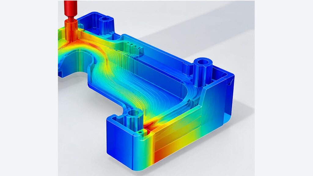
• Conduct Mold Flow Analysis to identify potential filling, packing and flow distribution, issues, and potential weld lines and warpage.
• Review test results of prototypes to establish loads and clearances for snap fits and assemblies.
• Perform tool trials to define mold variation and assess surface quality.
• Pilot production is used to define batch to batch variation and to define the process window.
Rapid prototyping (CNC and SLA) can demonstrate the function and appearance of the part but not necessarily test the injection molding process.
5. Balancing Tooling Cost, Part Performance, and Production Volume
Design for Injection Molding means trade-offs between tooling cost and part function.
| Design Decision | Technical Trade-Off | Cost Consideration |
| Thick Walls vs. Ribs | Material accumulation versus controlled reinforcement | Cooling time, resin consumption, defect risk |
| Straight-Pull vs. Side-Action Mold | Simple geometry versus functional undercuts | Tooling complexity, maintenance |
| Unfilled vs. Reinforced Resin | Ductility versus higher stiffness | Material cost, shrinkage control |
| Standard vs. Tight Tolerances | General dimensions versus critical precision | Inspection, scrap, process control |
| Prototype vs. Production Tooling | Design flexibility versus production durability | Upfront investment, expected volume |
For procurement approval, the engineering package must include:
• Released CAD files and materials specification.
• DFM and proposed tooling configuration.
• Critical dimensions and inspection plan.
• Tool-trial acceptance.
• Anticipated volume and quality targets.
Not the lowest tooling quote, but a functional solution at an acceptable total unit cost.
Closing Comments
Success in mechanical part design for injection molding, relies on a combined effort of various engineering disciplines to include structural, material, tooling and production validation.
LKK Design’s integrated mechanical design, DFM, prototyping, tooling and manufacturing services assist clients throughout the product development process to address the above challenges.
When your team requires a plastic enclosure or functional mechanical part for a production run, contact LKK Design for a no cost evaluation of your design for manufacturing (DfM) and practical design improvements prior to tooling investment.
FAQs
Q1. What mechanical design services does LKK Design provide?
LKK Design provides 3D CAD modeling, structural engineering, material selection, tolerance analysis, prototyping, and manufacturing support for product development.
Q2. How does LKK Design optimize parts for injection molding?
We review wall thickness, draft angles, ribs, bosses, undercuts, and tooling requirements through DFM analysis to identify potential manufacturing problems.
Q3. Can LKK Design help select materials for injection-molded parts?
Yes. We evaluate material properties, structural loads, environmental conditions, shrinkage behavior, and manufacturing costs to support material selection.
Q4. Does LKK Design provide DFM analysis before mold development?
Yes. Our DFM services evaluate part geometry, tooling feasibility, material selection, tolerance requirements, and potential manufacturing defects before tooling investment.
Q5. How does LKK Design address injection molding defects?
We use design reviews and manufacturing analysis to identify potential causes of sink marks, warpage, weld lines, and dimensional deviations.
Contact Us



- 20+ Design Industries Serviced
- 200+ Product Categories
- 1,000+ Industry Leaders Served
- 10,000+ Products Successfully Launched

Founder and Chairman of LKK Design Group
Ready to get started? Connect with us today!
 Talk to Our Team