

 Home /
Electronics Product Design Process for Hardware Startups: From Prototype to Mass Production


The Electronics Product Design Process for Hardware Startups involves more than schematic design and PCB fabrication. A functional prototype may still fail EMC testing, drain its battery prematurely, or develop assembly defects during production.
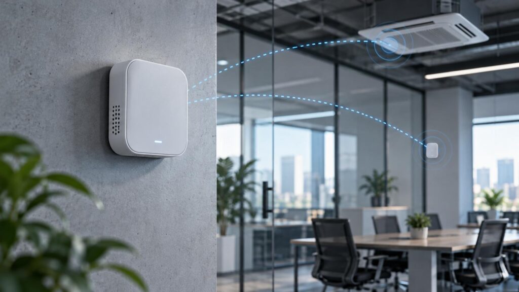
At LKK Design, we approach electronics development through measurable specifications, hardware–firmware integration, and manufacturing validation. The objective is to identify engineering risks before they become expensive design changes.
1. What goes Wrong With Electronics Prototypes
Sometimes, prototypes demonstrate performance under specific conditions. Production, however, requires systems to be performant across variations in components, environmental conditions, and batches of manufacturing.
Before engaging in schematic design, an Electronics Product Requirements Document (PRD) should specify the following:
• Electrical Specifications
• Functional Requirements
• Manufacturing Constraints
• Verification and Validation
An example would be specifying that “the battery should last 1 year,” without defining acceptance limits, testing conditions, and assumptions about the temperature or discharge of the battery.
Review of requirements should result in a preliminary risk register and test plan, as opposed to a simple feature prioritization.
2. Choosing MCUs, Power Architectures, and PCB Designs
Achieving Balance Between Power Consumption and Processing Resources
In hardware startups, one of the earliest design decisions made in architecture concerns future costs and technical flexibility.
When considering MCU choices, factors like Flash and RAM, Peripherals, RT Capability, and the support for OTA (Over-The-Air) firmware updates, should be considered. Systems requiring complex operating systems or high processing should utilize an MPU, but additional external memory may further increase system complexity.
Average Current in battery-powered electronics is calculated using:
Iavg = Σ(Istate × Duty Cycle)
Where:
• Iavg = Average Current in mA
• Istate = Current in state in mA
• Duty Cycle = fraction of time in state
Electronics designers should evaluate:
• Active, Standby, and Deep-sleep currents.
• Wireless transmission Duty cycle and peak currents.
• Efficiency of DC-DC converters and battery usage.
Temperature dependent discharge.
The layer count of PCB reflects signal speed, routing density and EMC requirements.
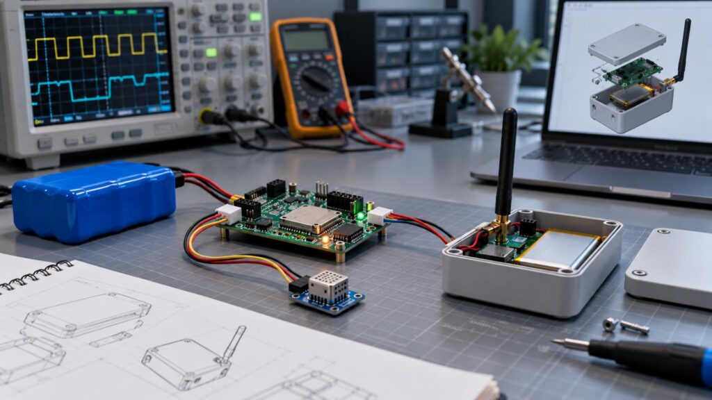
Decoupling helps to remove interference on the signal. Having return paths and controlled reference planes helps to reduce noise. All of these can be combined with using a four-layer PCB to help with system grounding and routing. Overall, the performance of the system is dependent on the layout and design of the system.
Verification of thermal constraints accounts for power dissipation of each device, the flow of air through the enclosure, and the flow of heat through the various pathways in the system.
3. Comparing Electronics Development Architectures
Different development stages warrant a different degree of customization.
| Technical Option | Suitable Application | Main Engineering Trade-off |
| Development Board | Early proof-of-concept | Fast firmware test; unsuitable size or unit cost |
| Pre-certified Module | BLE/Wi-Fi product development kits | Easy RF integration; integration constraints |
| Custom RF Design | Space/volume constrained products | More flexibility; more RF validation |
| 2-Layer PCB | Simple routing | Speed; cost; grounding; routing |
While using pre-certified modules can simplify development of wireless products, the same is not true for end-product compliance.
Startups should compare solutions using expected volume, development cost, PCB area, performance requirements, and certification workload.
4. Integrating PCB, Firmware, RF, and Mechanical Design
Integration of Electronic Hardware and Mechanical Design
Electronics cannot be finalized independently of mechanical design.
Where wireless components are placed (antenna placement, for example) can affect the reliability of a wireless connection. Metallic components can also affect assembly and reliability (e.g. mounting tolerances and thermal paths).
At LKK Design, we integrated multidisciplinary design team members to conduct design reviews to address the above needs.
Critical integration testing includes:
• RF: Test antenna signal (clearance) from final assembly.
• Firmware: Boot, memory stability, communication recovery, and OTA.
• Mechanical: PCB and connector mounts, thermal and service clearance.
• Supply Chain: Lead time of approved part, safety stock.
PCB testing and interface verification should be done prior to design freeze.
5. DFM, DFT, and EVT-PVT Validation
The design of the next generation of a product can change how the product is manufactured and serviced.
| Development Gate | Technical Focus | Required Evidence |
| EVT | Circuit functionality, electrical margins, power and interface behavior | Engineering test reports and issue logs |
| DVT | Environmental reliability, mechanical integration, EMC and design verification | Verified specifications and test records |
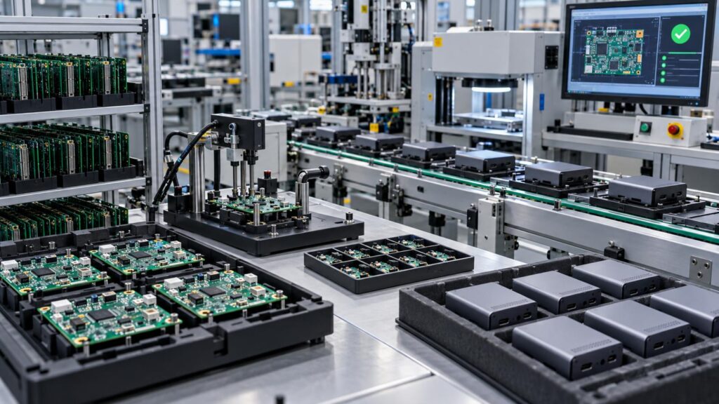
| PVT | Assembly repeatability, test fixtures, process stability and yield | Pilot-production data and release criteria |
At LKK Design, the development workflow connects prototyping, PCB engineering, firmware, and manufacturing reviews across these verification stages.
A working EVT prototype is not equivalent to a validated production process.
6. Verifying EMC, Wireless, and Product Safety Requirements
Starting to think about compliance during the design process is a good idea, and especially before finalizing PCB layout.
Depending on the function of the product and the market it is aimed for, the applicable requirements might be:
• FCC Part 15: Radio-frequency equipment requirements in the US.
• EU RED 2014/53/EU: Requirements for radio equipment (including RF, EMC and safety).
• RoHS: Restrictions of certain hazardous substances.
• IEC 62133-2 / UN 38.3: Safety and testing for the transportation of batteries.
EMC pre-compliance testing might help identify switching noise and other emission problems, as well as inadequate grounding.
Certification of modules does not remove the obligation to assess the integration of the module in the finished product.
For connected devices, it is important to evaluate cyber security as well as Firmware updates, in accordance with the regulations in target markets.
7. Evaluating Design Partners, BOM Costs and Production Readiness
In a Hardware Startup Electronics Product Design process, it is important to connect engineering decisions to purchasing economics.
While less expensive components may reduce the final cost of your product, various other considerations must be taken into account at the design phase. These include:
• Non-recurring engineering costs (NRE): expenses incurred for the design and development of electronic hardware and software.
• Recurring costs: PCB assembly and test.
• Quality costs: test failures, scrap, rework and warranty exposures.
• Supply Continuity: the reliability and the availability of components.
What Should an Electronics Design Partner Deliver?
Prior to signing a services agreement, review PCB design files, firmware, test procedures and verification documents.
Handover of products and production responsibility as well as ownership of intellectual property should be stipulated in agreements.
LKK Design supports PCB layouts, firmware development and prototyping. For manufacturing, we assist in product development, and recommend options for improvements.
We can review product requirements and assist startups in the Electronics Product Design Process to identify risks and define the next development milestone.
FAQs
Q1. What electronics product design services does LKK Design provide?
LKK Design offers hardware architecture, schematic design, PCB layout, embedded firmware development, prototyping, and manufacturing-oriented engineering support.
Q2. Can LKK Design help hardware startups develop products from initial concepts?
Yes. LKK Design supports product requirements definition, technical feasibility assessment, engineering design, prototype validation, and preparation for manufacturing.
Q3. Does LKK Design provide custom PCB design and PCBA prototyping?
Yes. LKK Design provides custom PCB development, including schematic design, component selection, PCB layout, prototype assembly, and functional verification.
Q4. How does LKK Design integrate hardware and embedded firmware?
LKK Design coordinates hardware architecture, firmware requirements, interface design, and prototype testing to identify compatibility issues before production.
Q5. Can LKK Design support IoT and wireless electronics development?
Yes. LKK Design offers IoT hardware engineering, wireless connectivity integration, embedded firmware development, and related software development services.
Contact Us



- 20+ Design Industries Serviced
- 200+ Product Categories
- 1,000+ Industry Leaders Served
- 10,000+ Products Successfully Launched

Founder and Chairman of LKK Design Group
Ready to get started? Connect with us today!
 Talk to Our Team