
 Home /
DFM Engineering Services for Robotics: Precision, Weight, and Assembly


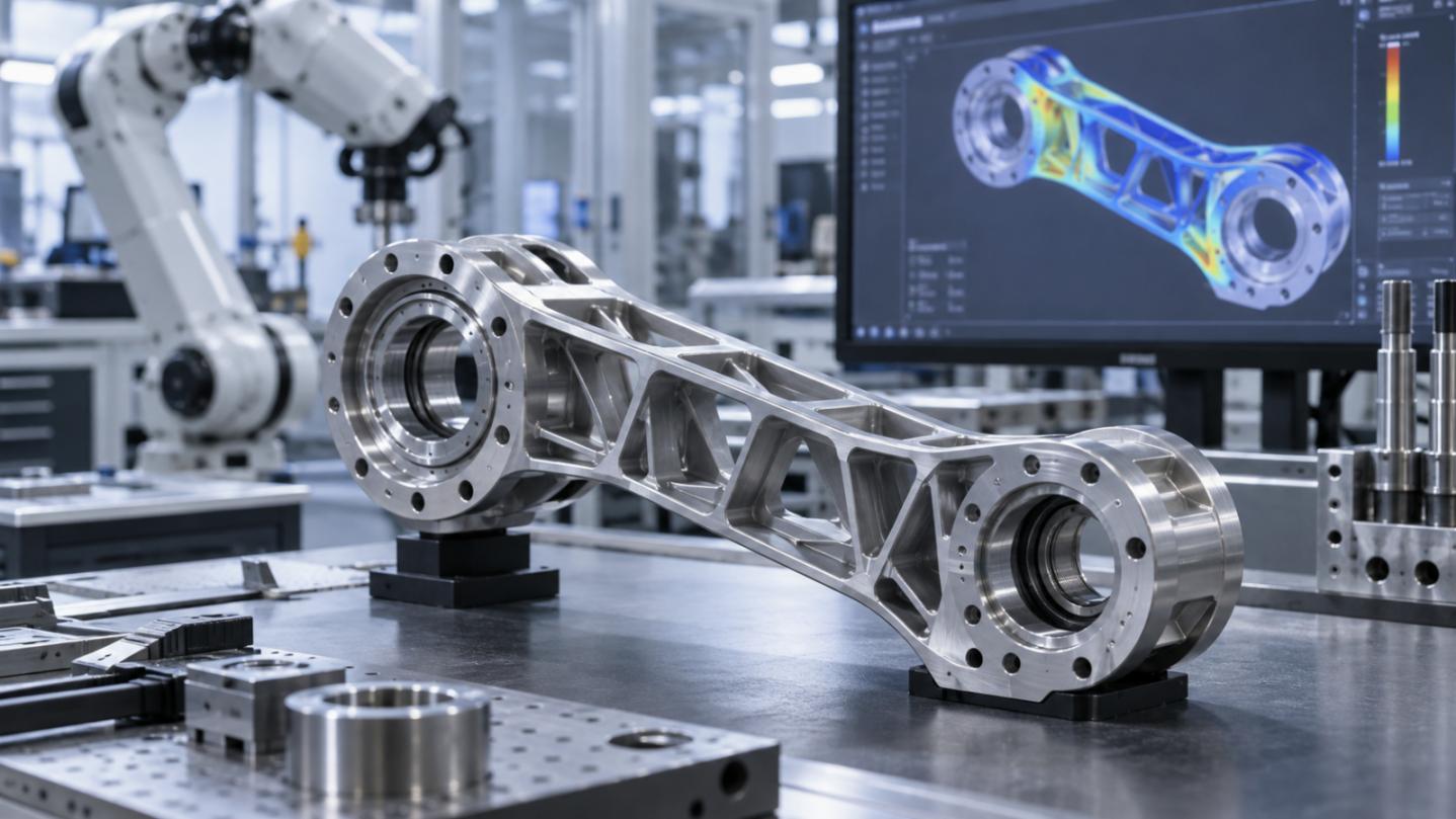

A robot joint housing can meet its dimensional drawing and still contribute to poor positioning, excessive friction, or inconsistent assembly. The problem may lie in datum selection, interface distortion, thermal growth, or tolerances that were never evaluated together.
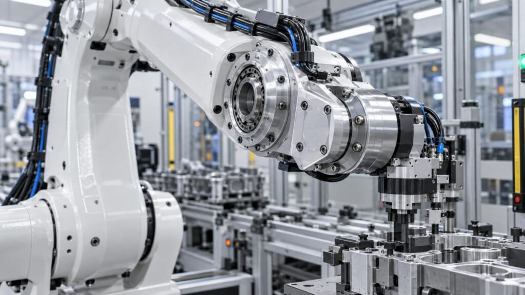
At LKK Design, our DFM Engineering Services connect geometry, manufacturing processes, assembly requirements, and cost. For robotics projects, the engineering brief must establish how each manufacturing decision supports the assembled mechanism.
Identify the Operating Condition Behind the Failure
Before changing a housing or link, distinguish three requirements:
• Positioning accuracy: Deviation from the commanded position.
• Repeatability: Consistency when returning under defined conditions.
• Settling time: Time required for residual motion to enter an acceptable band.
Record payload, center-of-gravity offset, working radius, acceleration, duty cycle, and temperature. Compare cold and warm operation, loaded and unloaded motion, and performance before and after reassembly.
DFM Engineering Services should establish whether the dominant problem comes from manufactured geometry, assembly variation, elastic deformation, or a system issue requiring calibration or control changes.
Allocate Tolerances from the Robot‘s Error Budget
Control Functional Relationships
For a simplified single-axis rotation:
Displacement ≈ distance from the axis × angular error in radians.
An illustrative 0.01° angular error at 500 mm produces approximately 0.087 mm displacement. Multi-axis analysis requires the actual robot configuration.
This explains why bearing-seat alignment and mounting-face orientation can matter more than tightening unrelated dimensions.
| Critical Feature | Functional Concern | Required Review |
| Bearing bore | Fit, roundness, and distortion | Size, form, inspection restraint, and assembly condition |
| Reducer mounting face | Axis tilt and uneven contact | Orientation, flatness, and fastening deformation |
| Locating pilot or dowels | Repeatable module positioning | Datum scheme, clearance, and constraint |
| Seal interface | Leakage and friction | Surface texture, geometry, and coating allowance |
Choose the Stack-Up Method Deliberately
Worst-case analysis evaluates tolerance extremes; statistical methods require justified assumptions about distributions and relationships between dimensions. Neither should conceal an unstable process.
Our DFM Engineering Services include critical-dimension identification, tolerance accumulation analysis, measurement accessibility, and process-capability target setting. Tight tolerances need a functional reason and a credible inspection method.
Reduce Inertia Without Sacrificing Stiffness
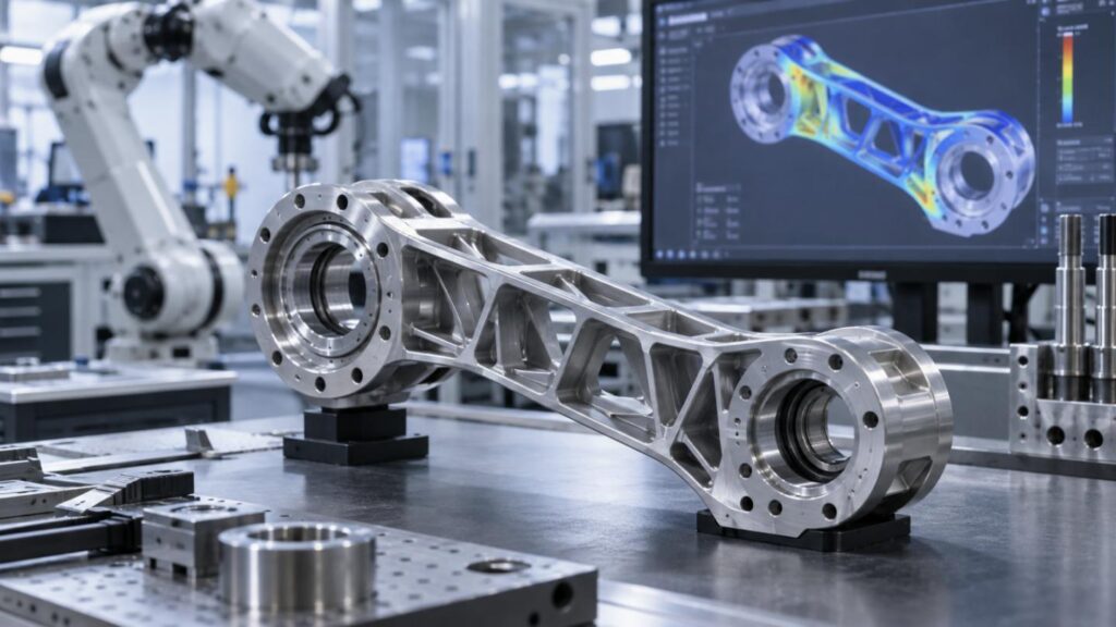
A higher-strength aluminum alloy may resist yielding better without materially increasing elastic stiffness. Likewise, removing equal mass near and far from a joint axis produces different inertia reductions.
Evaluate:
• Static Deflection: bending and torsion at challenging load points.
• Dynamic response:Structural modes, excitation, and settling.
• Manufacturing stability:tool access, clamping, chatter, and residual stress distortion.
• Durability: load cycles, stress concentration, and threaded-interface wear.
Thin walls may deform both during machining and bolting. Ribs and closed sections can retain stiffness, however they also may adversely affect, reach of cutting tool, casting, cleaning, and inspection. DFM Engineering Services must analyze the final geometry and its process in combination.
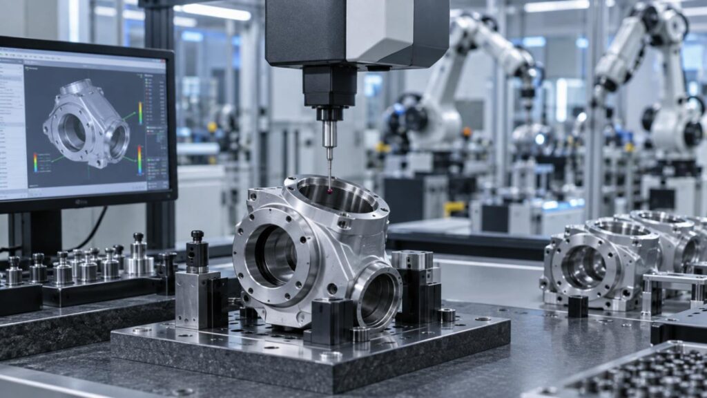
Compare Alternatives Under the Same Requirements
| Design Decision | Global Alternatives | Trade-Off |
| Structural material | Aluminum, Steel, hybrid inserts | Mass, stiffness, thermal mismatch, wear, and joining |
| Lightweight geometry | Thin walls, hollow sections, ribs | Inertia reduction, section stiffness, machining access, and vibration |
| Production route | CNC, casting plus machining, additive plus finishing | Quantity, revision frequency, tooling, defects, and verification |
| Housing architecture | Integrated or modular | Interface count, machining complexity, service access, and replacement cost |
| Location strategy | Clearance bolts, Dowels, pilots | Clamping, positional repeatability, thermal freedom, and overconstraint |
| Assembly strategy | Interchangeability, selective fitting, shims | Process capability, labor, traceability, and spare-part compatibility |
CNC may avoid dedicated casting tooling, however may result in significant material removal. Casting will require tooling allowances for distortion and critical interface machining. Additive routes will result in support removal, finishing, and validation of the material.
At LKK Design, DFM Engineering Services combine process-specific geometry review with volume-based cost analysis. Our coordination with industrial design helps preserve product appearance while modifying structures for manufacturing.
Match Interfaces to Bearings, Reducers, and Heat
Use the selected component manufacturer’s installation requirements. A bearing fit cannot be specified reliably from bore diameter alone.
Check load direction, rotating-ring conditions, housing stiffness, operating temperature, and the prescribed preload method. Account for coating buildup and define masked or subsequently machined surfaces.
Backlash compensation does not eliminate twist or transmission error. Cold measurements can pass, and thermal expansion can still change fits and preload.
Review the thermal expansion of cable paths and the space allowed for cable bending. Also review connector access, and review the structural interaction with motion control.
Design for Controlled Assembly and Replacement
DFM Engineering Services should define:
• Locating features separately from clamping functions.
• Fastening sequence, torque conditions, and contact-surface preparation.
• Tool clearance, bearing extraction, and cable replacement paths.
• Inspection points before interfaces become inaccessible.
• Reassembly checks and any required recalibration.
Selective fitting may support prototypes, but it creates production and spare-part obligations. Record such adjustments explicitly.
Verify Geometry, Motion, and Production Consistency
CMM inspection establishes geometric evidence; it does not establish robot positioning performance.
Combine drawing inspection with loaded motion, thermal stabilization, vibration, and repeated-assembly testing. Document measurement uncertainty, test conditions, and acceptance limits.
ISO 9283 addresses industrial robot performance and related testing. Apply the agreed drawing conventions and assess relevant safety requirements separately. Management-system certification is not a robot-performance certificate.
Scope DFM Engineering Services Around Acceptance
Request a prioritized risk register, proposed changes, critical characteristics, process comparisons, and verification responsibilities. Confirm whether revised CAD, drawings, simulations, prototypes, and revision rounds are included.
Compare total costs: engineering, tooling, inspection, assembly, scrap, maintenance, and supplier transfer. Agree on confidentiality, ownership, and change control.
Share your CAD, interface specifications, load cases, and production forecast with LKK Design’s DFM Engineering Services team. These inputs support a focused review of the changes needed before prototype approval or production release.
FAQs
Q1. What Do LKK Design’s DFM Engineering Services Include?
LKK Design reviews part geometry, material selection, tolerance accumulation, tooling feasibility, assembly requirements, and manufacturing costs. Deliverables include a prioritized DFM report, with revised CAD files and engineering change documentation available depending on the agreed scope.
Q2. What Files Should I Prepare for a Robotics DFM Review?
Provide 3D CAD files, available engineering drawings, material specifications, and production quantities. For robot components, include payloads, operating temperatures, critical interfaces, and bearing or reducer installation requirements so the review reflects actual operating conditions.
Q3. Can LKK Design Help Reduce the Weight of Robot Components?
LKK Design can review geometry, wall thickness, and material alternatives for manufacturing feasibility. Define stiffness, interface, and durability requirements before approving weight reductions. Confirm whether structural analysis and physical testing are included in the project scope.
Q4. How Does LKK Design Evaluate Tolerance Accumulation?
LKK Design offers worst-case or statistical tolerance stack-up analysis for critical dimensions. For a robot joint, the review should connect bearing seats, mounting faces, and locating features to assembly requirements. The selected method depends on design risks and available process data.
Q5. Which Manufacturing Processes Can LKK Design Assess?
LKK Design offers DFM capabilities include CNC machining, die casting, injection molding, and sheet metal. Process selection considers geometry, material, production volume, tooling investment, and quality requirements. Critical robot interfaces may require secondary machining and inspection.
Contact Us



- 20+ Design Industries Serviced
- 200+ Product Categories
- 1,000+ Industry Leaders Served
- 10,000+ Products Successfully Launched

Founder and Chairman of LKK Design Group
Ready to get started? Connect with us today!
 Talk to Our Team