

 Home /
 3D Mechanical Design for Custom Hardware Products: Designed to Scale


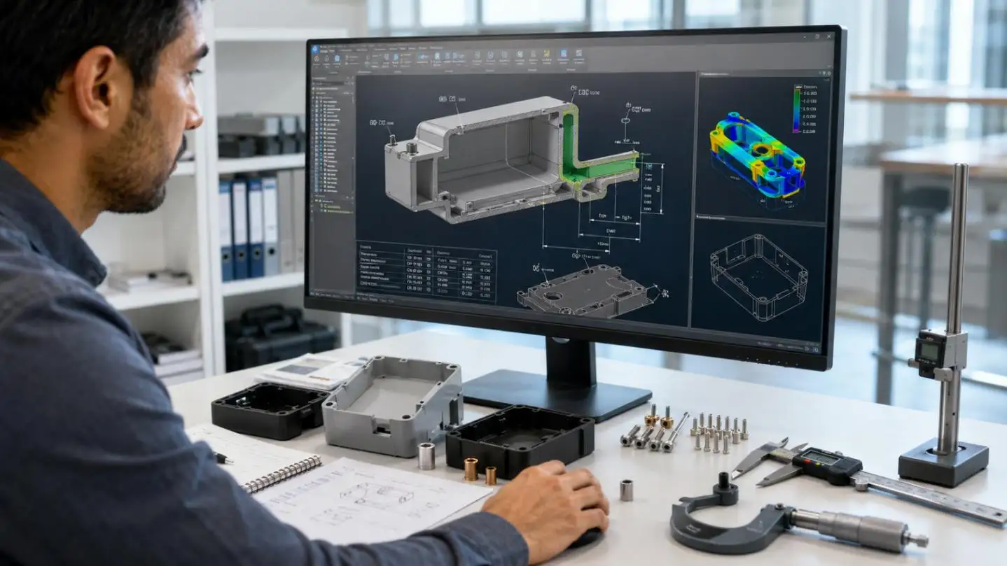

A CAD model can look complete and still fail during molding, assembly, testing, or pilot production. 3D mechanical design for custom hardware products must control fit, load paths, heat, sealing, and manufacturing variation. The real output is a product definition that a factory can build and inspect repeatedly.
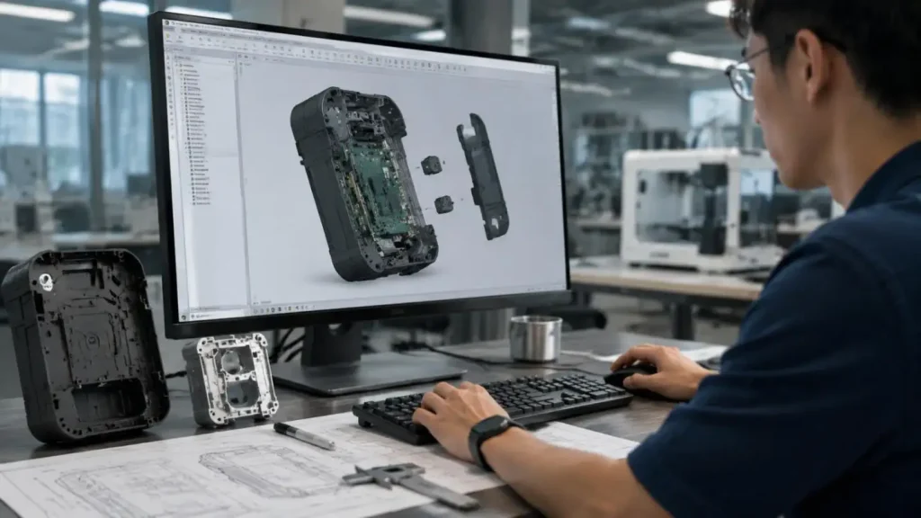
Production Risk Starts With Undefined Requirements
Mechanical design should begin with failure conditions, not exterior surfaces. Before geometry is frozen, the product brief needs three connected records:
• Interface control: PCB outline, connector centerlines, display window, battery volume, antenna keep-out zones, cable exits, and mounting datums.
• Operating profile: Temperature range, drop height, vibration spectrum, ingress target, chemical exposure, duty cycle, and required service life.
• Manufacturing case: Prototype quantity, annual volume, cosmetic requirements, target cost, assembly method, and intended production process.
LKK links these inputs across industrial design, mechanical design, electronics, and tooling, reducing the risk that a late PCB, material, or connector change invalidates the enclosure and mold strategy.
Engineering Logic in 3D Mechanical Design For Custom Hardware Products
Tolerances Must Follow Function
Critical-to-function dimensions should be referenced from functional datums, not from convenient model edges. Consider an assembly with four independent dimensions, each controlled to ±0.15 mm:
• Worst-case stack: ±0.60 mm
• RSS estimate: ±0.30 mm
Worst-case analysis suits interfaces where failure is unacceptable. RSS requires centered, stable, statistically independent processes. Monte Carlo is better for nonlinear geometry or non-normal distributions. LKK applies GD&T and RSS or worst-case stack-up analysis before drawing release.
Material Changes Are Dimensional Changes
Thermal growth follows:
[\Delta L=\alpha L\Delta T]
A 200 mm housing with a CTE of 80 × 10⁻⁶/K grows 0.80 mm over 50 K; a metal part at 23 × 10⁻⁶/K grows 0.23 mm. That 0.57 mm mismatch can shift connectors, preload a PCB, or reduce gasket compression. Final calculations require grade-specific material data.
Wall thickness, ribs, bosses, radii, draft, and undercuts must follow material flow and load paths. Thickening a molded wall may increase sink and warpage; a controlled rib can add stiffness with less cosmetic risk.
Compare the Mechanical Route Before Tooling
| Decision | Options | Engineering Trade-Off |
| Production process | 3D printing, CNC, sheet metal, injection molding, die casting | Compare material fidelity, geometry, tooling, finish, volume, and unit cost. A printed prototype cannot validate molded shrinkage. |
| Enclosure material | Polymer, machined aluminum, sheet metal, die-cast alloy | Balance impact, creep, weight, heat transfer, EMC, antenna transmission, and corrosion. |
| Joining method | Screws/inserts, snap-fits, adhesive, welding | Compare torque control, removal cycles, sealing, automation, and repairability. |
| Tolerance method | Worst-case, RSS, Monte Carlo | Select by failure severity, process data, distribution stability, and acceptable assembly risk. |
This comparison is central to 3D mechanical design for custom hardware products. LKK's DFM and DFA reviews cover draft, wall uniformity, weld-line risk, sliders, tool clearance, part count, fastening, and assembly sequence.
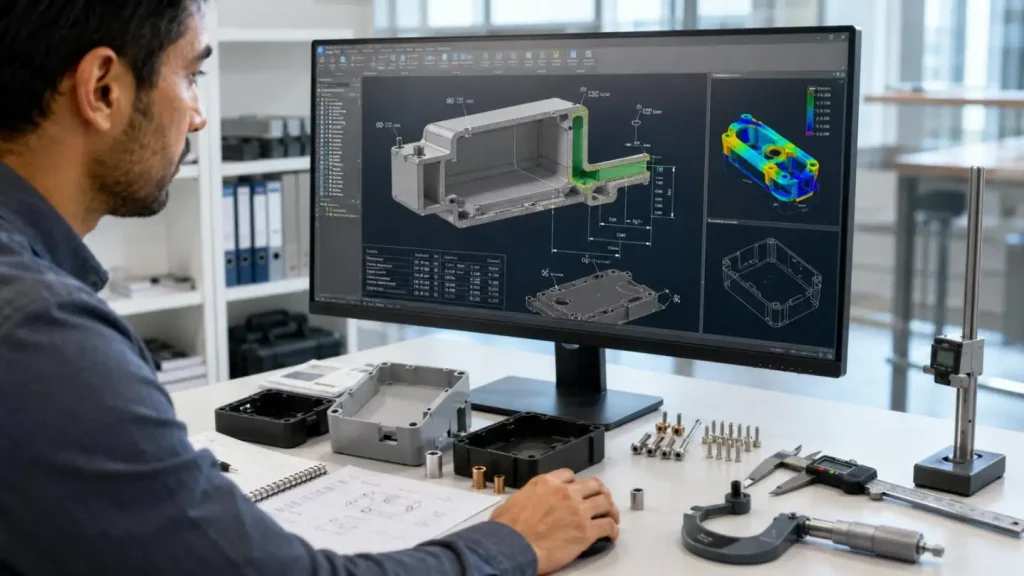
Match Structure, Electronics, Heat, and Sealing
An enclosure is part of the electrical and thermal system. An 8 W heat source at 5 K/W total thermal resistance produces a calculated 40 K rise before local hot spots. A metal spreader may lower temperature but disturb an antenna or create an EMC path, so thermal, RF, and structural decisions remain coupled.
Risks associated with assembly tolerances and joint function include molding variations and creep. Clearance for tightening fasteners, as well as flatness within tolerance requirements, is necessary for allowable joint function. LKK has developed a variety of analysis techniques to address these risks including FEA, thermal analysis and CFX, as well as tolerancing and environmental prototypes.
Assembly and Maintenance Should be Included in the CAD Model
Geometry ready for production must demonstrate the movement of tools, fixtures, and replacement parts in and throughout the product. Check that:
• Screwdrivers and automated drivers have access without contacting cables.
• Locating features prevent reversed PCB or battery installation.
• Cable bend radius and strain relief survive repeated assembly.
• Seals, batteries, and PCBs can be replaced and correctly reassembled.
• Coating thickness and insert installation are included in the tolerance chain.
LKK supports assembly workflow tests, SOPs, First Article Inspection requirements, and Engineering Change Notice tracking.
Validate the Design and Production Process
3D mechanical design for custom hardware products should pass three different evidence gates:
| Gate | What It Must Prove |
| EVT | Core mechanisms, interfaces, structural margins, and thermal concept work |
| DVT | Final materials and geometry meet drop, vibration, thermal-cycle, ingress, and functional requirements |
| PVT | Tooling, assembly, inspection, process capability, and pilot output are repeatable |
LKK's prototyping capabilities include CNC prototypes to ±0.05 mm with Ra ≤0.8 μm and sheet-metal hole positioning to ±0.1 mm, subject to geometry and material. These figures should not be copied directly onto every production drawing.
Each critical dimension requires:
• An agreed inspection method
• A defined sample plan
• A measurement datum
• A production capability target
LKK identifies Cpk ≥1.67 as a trial-molding target for defined critical characteristics.
Standards and Procurement Evidence
All drawings should be aligned to either ASME Y14.5 or the appropriate ISO GPS standard, including ISO 1101. IEC 60529 describes IP classifications, nonetheless, CAD geometry cannot verify an IP rating. The requirements for RoHS, REACH, CE, FCC, medical, automotive, and machinery standards, among others, will depend on the product and the target market.
A like-for-like quote should detail:
• Native CAD, STEP files, 2D drawings and BOM
• GD&T, DFM reports and the extent of simulation
• Prototype rounds and test reports
• ECN and design-revision responsibilities
• Tooling and pilot-production support
• Acceptance criteria and IP ownership
LKK associates requirements to all test and production ramp stages of delivery using EVT, DVT, PVT, and production ramp-up.
To facilitate a detailed review of the 3D mechanical design for custom hardware products, LKK will require the product brief, PCB data, expected volume, operating environment, compliance market, and known failure risks. This will allow the engineering team to review the data and make a feasibility assessment and provide a cost estimate for geometry and tooling.
FAQs
Q1. What prototyping methods does LKK offer?
Method selection by LKK is dependent on whether the prototype is required to validate the appearance,fit, function, behavior of the proposed material, or the level of readiness of the proposed production route. The available processes include: CNC Machining, SLA, SLS, MJF, vacuum casting, sheet metal fabrication, and rapid tooling.
Q2. Can LKK work with an existing CAD model or prototype?
Yes, they can. LKK can analyze CAD files along the lines of appearance models, functional prototypes, and incomplete engineering designs. These analyses may reveal potential risks in the domains of tolerance, material selection, assembly, tooling, and systems integration.
Q3. How does LKK integrate DFM into mechanical design?
LKK carries out a review of drawings at the stage just prior to tooling release and considers the wall thickness, draft, ribs, bosses, undercuts, parting lines, gates, and weld lines. Tooling access and the selection of fasteners for assembly are reviewed.
Q4. Which manufacturing processes can LKK design for?
LKK offers Design for Manufacturing (DFM) services for processes such as injection molding, die casting, CNC machining, sheet metal fabrication, 3D printing, vacuum casting, and rapid tooling. The actual process to be employed depends on the material, geometry, Requirement, volume, finish, and cost.
Q5. Does LKK provide tolerance and GD&T analysis?
Yes. LKK can prepare drawings based on GD&T, perform worst-case or RSS analysis to determine the stack-up of tolerances on critical assemblies, and identify functional dimensions that are essential for a given function.
Contact Us



- 20+ Design Industries Serviced
- 200+ Product Categories
- 1,000+ Industry Leaders Served
- 10,000+ Products Successfully Launched

Founder and Chairman of LKK Design Group
Ready to get started? Connect with us today!
 Talk to Our Team


