

 Home /
 Design for Assembly and Manufacturing Guidelines: Tolerance Management


Table of Contents


A product may work as a prototype yet remain unsuitable for repeatable production. Shrinkage, coating thickness, fixture access, operator handling, and machine variation become critical at volume. Effective Design for Assembly and Manufacturing Guidelines connect geometry with process capability, assembly, inspection, service, and purchasing evidence before tooling release.
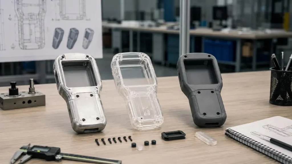
Production Failures Usually Begin at Interfaces
Four mating dimensions at ±0.10 mm each can create significantly different assembly outcomes depending on the calculation method.
| Analysis Method | Result | Application Condition |
| Worst-case stack-up | ±0.40 mm | Assumes all dimensions reach their limits simultaneously |
| RSS analysis | Approx. ±0.20 mm | Requires independent, stable and statistically centered processes |
Rather than tightening every tolerance—which can increase machining, tooling and inspection costs—designers should:
• Establish functional datums
• Identify critical-to-quality dimensions
• Map the dimensional loop controlling final fit
• Apply tighter tolerances only to functional interfaces
• Verify that the measurement system can resolve the specified tolerance
LKK supports early validation through complementary prototype processes:
| LKK Process | Technical Capability | Suitable Evidence |
| CNC machining | ±0.05 mm; Ra ≤0.8 μm | Dimensional fit, surface quality and mechanical assembly |
| Vacuum casting | 50–200 parts; ABS-like, PC-like, transparent or Shore A 50–90 materials | Low-volume assembly and material-behavior evaluation |
These prototypes provide useful geometric and assembly evidence but cannot fully reproduce injection-molding shrinkage, weld lines, ejection stress, warpage or long-run process variation.
Connect DFM, DFA, Quality, and Cost
Professional Design for Assembly and Manufacturing Guidelines treat manufacturability as a system.
| Review | Engineering Question | Evidence |
| DFM | Can the geometry be produced by the selected process? | Draft, wall and tool-access analysis |
| DFA | Can parts be located, joined and inspected efficiently? | Assembly sequence and error-proofing review |
| DFQ | Can critical characteristics be controlled? | CTQs, tolerance stack and Gauge R&R |
| DFC | Does the design meet lifecycle cost targets? | Tooling, labor, scrap and volume-cost model |
Part reduction helps only when it does not introduce costly side actions, difficult machining, material waste, or poor serviceability.
Compare Joining Methods Before Freezing the Architecture
| Joint | Best Use | Production Risk |
| Screws | Serviceable modules and controlled clamp load | Torque errors, tools and loose hardware |
| Snap-fits | Rapid assembly with few added parts | Creep, resin sensitivity and limited opening cycles |
| Adhesives | Continuous or mixed-material joints | Preparation, curing and difficult inspection |
| Ultrasonic welding | Permanent thermoplastic joints | Joint design, material compatibility and equipment |
One-piece architecture reduces handling and inventory. Modular architecture is preferable when batteries, PCBs, seals, wear parts, or regional variants need replacement. The decision must balance assembly time, tooling complexity, structural load, ingress protection, repair strategy, and total cost.
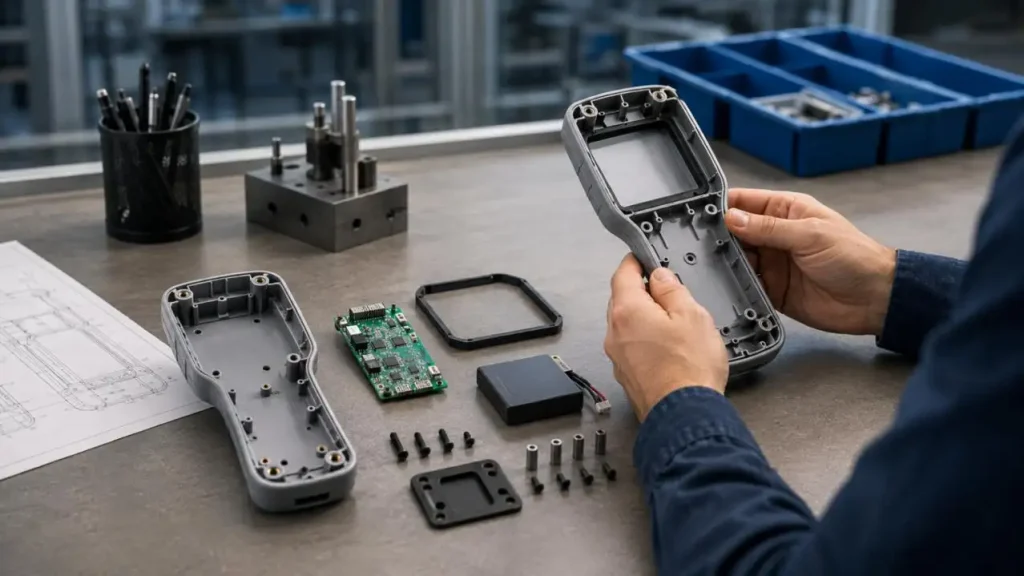
Match the Rules to the Manufacturing Process
The same Design for Assembly and Manufacturing Guidelines cannot be applied unchanged across processes.
| Process | Production-Critical Design Decisions | Relevant LKK Capability |
| Injection molding | Wall uniformity, draft, ribs, gates, weld lines and undercuts | Up to 1,500-ton clamping, 32-cavity molds and ±0.05 mm part tolerance |
| Mold tooling | Parting, ejection, cooling balance and insert access | S136 tooling, hot runners, ±0.005 mm critical mating-surface accuracy and 100,000+ stated cycles |
| CNC | Cutter access, internal radii, feature depth and setup count | Prototype machining to ±0.05 mm and Ra ≤0.8 μm |
| Sheet metal | Bend radius, K-factor, springback, relief and weld access | ±0.5° bend-angle and ±0.1 mm hole-position accuracy |
| Electronics | PCB retention, connector keep-outs, ESD, routing, heat and EMC spacing | SMT handling from 01005 chips to 60 mm irregular components |
Surface finishing belongs in the tolerance model. LKK's spray-painting process controls film thickness to ±5 μm; accumulated coatings can still alter snap engagement, grounding, seal compression, and cosmetic gaps.
Design for Assembly, Installation, and Service
Suitable DFA reduces reorientation and makes incorrect assembly difficult. Designers should provide:
• A dominant assembly direction and stable locating features
• Keyed parts and connectors to prevent reversal
• Common, captive fasteners with tool clearance
• Reachable test points and visible connector mating
• Replaceable batteries, seals, filters, and PCBs
• Inspection features accessible in production fixtures
LKK reviews part count, fastening, standard-component substitution, robotic pick-and-place feasibility, access clearance, and tolerance stack-up. Field installation adds mounting envelopes, cable bend radius, safe disconnection, seal replacement, and permitted reassembly cycles.
Verify the Design Before Tool Release
A credible application of Design for Assembly and Manufacturing Guidelines ends with evidence. Drawings should use a defined ISO GPS or ASME Y14.5 convention. The supplier package should contain a DFM risk matrix, FMEA, CTQ plan, tolerance analysis, First Article Inspection criteria, SOPs, control plan, and ECN history.
Validation is a phased approach as follows:
• EVT: Check the function, interfaces, loads, thermal behavior, and address engineering issues.
• DVT: Design is now fixed. Conduct tests on dimensions, environment, reliability, and compliance.
• PVT: Validate tooling and work stations, as well as inspection, yield of takt time and pilot.
• MP: Evaluate capability, scrap, rework, and unexpected maintenance. Also, assess changes that were approved.
For the specified LKK mold trials, validation can consider variation of pressure and temperature to be in the range 2% and Cpk to be ≥ 1.67 for the agreed upon critical dimensions. This criterion is applicable only when the sampling plan, process conditions, CTQ, and measurement capability have been documented.
ISO 9001 supports general quality management. ISO 13485 and IATF 16949 apply only when the certified site and scope cover the project. CE, FCC, RoHS, REACH, IEC, and IPC requirements must be selected by product and destination market.
Freeze Engineering Evidence Before the Purchase Order
A production RFQ should include controlled 3D files, GD&T drawings, BOM, materials, finishes, annual volume, CTQs, target markets, inspection methods, packaging, and acceptance limits. The quote should separate tooling, fixtures, NRE, unit cost, inspection, maintenance, pilot quantity, and engineering-change ownership.
LKK combines industrial design, mechanical and electronic engineering, prototyping, tooling, manufacturing engineering, and 5,000+ supply-chain partners. This can reduce handoff risk, but every gate should still close with objective evidence.
Applied early, Design for Assembly and Manufacturing Guidelines convert a manufacturable concept into a controlled production system. Teams approaching tooling or pilot production can submit CAD, BOM, volume, and CTQs to LKK for a focused DFM/DFA review.
FAQs
Q1. What does LKK consider during a DFM and DFA review?
During DFM/DFA reviews, LKK assesses draft angles, uniformity of walls and undercuts, locations of gates and bosses, snap-fits, tool access, part count and assembly, as well as methods and sequences of assembly, joining methods, and robotic assembly along with the tolerance stack up.
Q2. Which manufacturing processes does LKK offer?
LKK offers injection molding, CNC machining, die casting, sheet metal fabrication, SMT, surface finishing, tooling and final assembly.
Q3. How does LKK manage dimensional variation?
LKK performs CTQ identification, functional datums, worst case or RSS tolerance analysis, Gauge R&R, inspection and process capability planning.
Q4. What are the prototype CNC capabilities of LKK?
LKK's prototype CNC process controls dimensional tolerances of around ±0.05 mm and surface roughness of Ra ≤0.8 μm for appropriate metals and engineering plastics.
Q5. Does LKK support low-volume prototype production?
Yes. LKK's silicone vacuum casting performs approximately 50–200 pieces using ABS-like, PC-like, transparent and Shore A 50–90 materials.
Contact Us



- 20+ Design Industries Serviced
- 200+ Product Categories
- 1,000+ Industry Leaders Served
- 10,000+ Products Successfully Launched

Founder and Chairman of LKK Design Group
Ready to get started? Connect with us today!
 Talk to Our Team