

 Home /
 Mold Making Process From DFM To Trial Molding for Stable Production

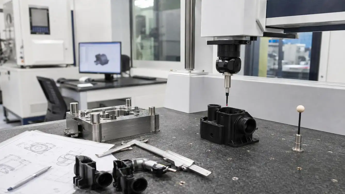
Table of Contents


A reliable Mold Making Process From DFM To Trial Molding does more than convert a 3D model into steel. It connects product geometry, polymer behavior, mold architecture, machining accuracy, injection-machine capability and measurable acceptance criteria.
Many expensive tooling problems begin before machining: the resin grade is not frozen, critical dimensions lack datums, cosmetic zones conflict with gate locations, or the quoted mold cannot run on the intended press. Correcting these issues after T0 may require welding, re-machining or replacing inserts.
DFM Must Convert Product Risks Into Mold Decisions
A release-ready DFM should identify not only whether a feature can be molded, but how it affects filling, cooling, ejection and dimensional stability.
Key reviews include:
•Wall transitions: Thick-to-thin flow paths increase pressure loss; local thick sections cool slowly and create sink or voids.
•Ribs and bosses: As an initial guideline, rib thickness is often controlled near 50–60% of the adjoining wall, but the final ratio must reflect resin, appearance and structural loading.
•Draft and texture: Smooth surfaces may begin around 0.5–1° draft, while deeper textures generally require more. Texture depth, resin shrinkage and draw direction must be reviewed together.
•Undercuts: Each slider, lifter, collapsible core or unscrewing mechanism adds cost, wear points and cycle time.
•Steel-safe dimensions: Critical shutoffs, snap fits and mating dimensions should initially retain removable steel where practical, because cutting steel is easier to control than welding it back.
LKK supports this stage with draft, wall-thickness and tolerance analysis, gate and ejection planning, slider-complexity assessment and a prioritized DFM risk matrix. This links product changes directly to tooling consequences before steel is ordered.
Flow, Packing and Cooling Control the Final Geometry
The technical logic behind the Mold Making Process From DFM To Trial Molding is a chain of interacting variables:
Geometry→Flow Resistance→Cavity Pressure→Packing→Shrinkage and Warpage
Thin sections raise the pressure needed to reach the end of fill. If the gate freezes before the thick region is adequately packed, additional hold time cannot prevent sink. Cooling time also rises approximately with the square of effective wall thickness, making isolated heavy sections potential cycle-time bottlenecks.
Gate position determines flow length, weld-line location, packing efficiency and fiber orientation. In glass-filled materials, different flow-direction and transverse shrinkage values can produce asymmetric warpage even when the cavity was scaled with the material supplier's average shrinkage value.
Cooling should therefore be evaluated through circuit layout, flow, pressure drop and cavity-surface temperature distribution—not inlet-water temperature alone.
Compare Mold Architectures Against Production Requirements
No mold solution is universally superior. The correct architecture depends on volume, resin, appearance, automation and maintenance capability.
| Decision | Lower-Complexity Option | Higher-Capability Option | Engineering Trade-Off |
| Cavities | Single cavity | Balanced multi-cavity | Tool cost versus output and cavity balance |
| Runner | Cold runner | Hot runner or valve gate | Material loss versus temperature-control complexity |
| Gate access | Two-plate mold | Three-plate mold | Simplicity versus flexible gate placement |
| Undercut release | Slider or lifter | Unscrewing/collapsible core | Stroke and wear versus complex geometry |
| Tool steel | Pre-hardened steel | Hardened or corrosion-resistant steel | Easier modification versus wear and corrosion resistance |
| Cooling | Drilled water lines | Conformal cooling | Lower investment versus improved hotspot control |
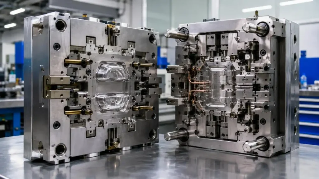
LKK integrates standard DME/HASCO mold-base selection, hot-runner planning, conformal-cooling evaluation and structural FEA. These capabilities are most valuable when used to justify a project-specific solution rather than automatically specifying the most expensive architecture.
Match the Mold to the Injection Molding System
Before mold-design approval, the tool must be checked against the intended press.
An initial lock-force estimate can be expressed as:
Fclamp=Aprojected×Pcavity×S
The projected area should include all cavities and runners. Cavity pressure and the safety factor must reflect the resin, wall thickness, gate design and expected pressure balance.
Machine matching should also confirm:
•Shot weight with resin-density conversion, not only the machine's PS-rated capacity
•Tie-bar spacing, platen size and permitted mold height
•Locating ring, nozzle radius, sprue diameter and ejector pattern
•Hot-runner voltage, connectors and control zones
•Cooling-water capacity, robot access and part-removal direction
LKK's integrated workflow connects DFM, tooling and injection-molding planning, reducing the risk of a tool that operates at the mold builder but becomes difficult to transfer to the production plant.
Machining Sequence Protects Designed Accuracy
In a controlled Mold Making Process From DFM To Trial Molding, accuracy is created through staged material removal rather than a single finishing operation.
LKK's referenced cavity-machining sequence uses approximately 0.3 mm finishing stock after roughing and 0.1 mm after semi-finishing before final machining. Critical production stages include:
- Steel verification, rough machining and stress control
- Heat treatment where required
- Precision CNC finishing
- Electrode production and EDM for deep or narrow features
- Wire-cut EDM for inserts and special profiles
- Grinding, fitting, polishing and texture preparation
- CMM, surface and material verification before assembly
LKK reports five-axis CNC capability for critical mold features, precision electrode and wire EDM processing, CMM inspection and alloy verification. The appropriate tolerance must still be assigned feature by feature; equipment resolution alone does not guarantee molded-part capability.
Installation and Maintenance Affect Trial Results
A poor setup can appear to be a mold defect. Before T0, technicians should verify alignment, nozzle contact, ejector stroke, slide movement, hot-runner wiring and cooling connections.
LKK's referenced assembly controls include core/cavity alignment checks and a 0.5 MPa, 30-minute cooling-circuit pressure test. Maintenance planning should additionally define lubrication intervals, seals, wear inserts, ejector components, hot-runner spares and storage protection.
Use T0 to Establish a Process Window
Trial molding should begin with the specified, correctly dried resin. A short-shot study reveals filling sequence and cavity imbalance before packing pressure hides the evidence.
The trial should then establish:
•Velocity-controlled filling and transfer position
•Peak pressure and available pressure margin
•Hold pressure and gate-freeze time
•Cavity-specific part-weight stability
•Mold temperature, cooling time and dimensional response
•Cosmetic defects under defined lighting conditions
If a defect disappears only at an extreme pressure or temperature, the mold may lack a robust production window. T0 should separate process corrections from required changes to gates, vents, cooling, shutoffs or product geometry.
LKK combines trial molding with dimensional, surface and process-stability evaluation. A capability target such as Cpk ≥1.67 can be used for agreed critical dimensions, but only after the material, machine, process window, conditioning time and measurement system are fixed.
Validate the Tool Before Purchase Approval
T0, T1 and T2 are project labels, not acceptance criteria. Each round's contract should determine objective and deliverables. Dimensional acceptance may refer to ISO 20457:2026, while shrinkage studies may use ISO 294-4 or ASTM D955. Certain automotive or medical projects may also need to have PPAP, traceability, or documented process validation.
A successful Mold Making Process From DFM To Trial Molding ends with more than approved samples. Buyers should receive mold drawings, BOMs, steel records, trial parameters, dimensional reports, maintenance instructions and spare-parts lists. For projects requiring coordinated DFM, precision tooling and production validation, LKK can review the product data and develop a mold plan aligned with the required volume, machine and acceptance criteria.
FAQs
Q1. Does LKK examine product designs before mold production?
Yes. LKK's DFM reviews draft angles, wall thicknesses, tolerances, undercuts, parting lines, gates, ejection, cosmetic surfaces, and the feasibility of multi-cavity designs. Issues found can be placed in a DFM risk matrix prior to the cutting of steel.
Q2. What does LKK need for a mold estimation?
Buyers should provide a 3D STEP file, dimensioned drawings, resin grade, surface finish, critical tolerances, annual requirement, expected mold life, and the type of injection machine. Buyers should also provide assembly and regulatory requirements.
Q3. Can LKK assist in determining the appropriate cavity count?
Yes. LKK can evaluate the trade-offs of single, multi, or family molds based on annual demand, desired cycle time, balance of cavities, expected tooling cost, the capacity of the injection machines, and desired flexibility of production.
Q4. Does LKK offer both cold and hot runner molds?
LKK is capable of cold and hot runner mold fabrication. LKK recommends cold runner molds for processes that use low viscosity resins that can be easily 'bled' from the mold cavity. LKK recommends hot runner molds that require little gate waste with high frequency color changes and significant machine Automation.
Q5. What type of mold steels can LKK work with?
LKK works with tool steel H13, S136, and NAK80. The stainless steel selection should depend on the resin material being used, the expected lifetime of the mold, the surface finish, the roughness of the material, and the expected lifecycle of the mold.
Contact Us



- 20+ Design Industries Serviced
- 200+ Product Categories
- 1,000+ Industry Leaders Served
- 10,000+ Products Successfully Launched

Founder and Chairman of LKK Design Group
Ready to get started? Connect with us today!
 Talk to Our Team