

 Home /
 CNC Prototype vs. Injection-Molded Prototype: Choosing the Right Validation Evidence


A CNC-machined enclosure can fit every component and still fail after injection molding. The molded version may warp, develop sink marks around bosses, or crack across a weld line. This is why CNC prototypes vs. injection-molded prototypes should be evaluated by the evidence each process produces—not simply by price, precision, or lead time.
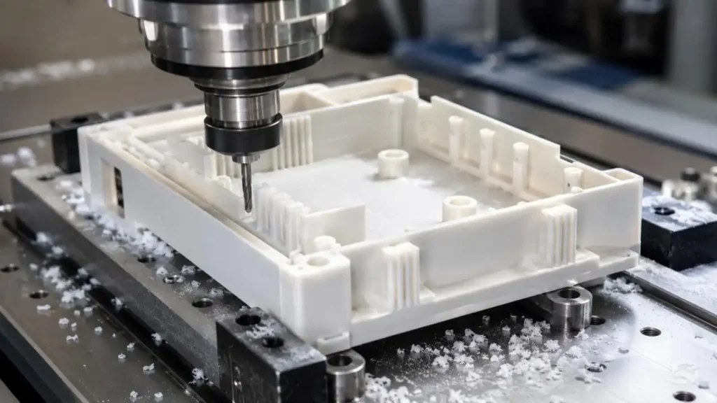
CNC machining is primarily a geometry-validation process. Prototype injection molding introduces material flow, packing, cooling, shrinkage, and ejection—the same physical mechanisms that influence production parts.
Why an Accurate CNC Part May Not Predict Molded Performance
CNC machining removes material from solid stock. Injection molding heats resin, forces it through a gate, packs the cavity, and cools the part under constrained conditions. The manufacturing history is fundamentally different.
| Validation Question | CNC Prototype | Injection Molded Prototype |
| Do components and interfaces fit? | Strong evidence | Strong evidence after shrinkage correction |
| Will thin walls fill completely? | Cannot prove melt flow | Reveals short shots and pressure limits |
| Will bosses or ribs create sink marks? | Not reproduced | Visible during mold trials |
| Where will weld lines form? | No weld lines | Determined by gate and flow pattern |
| Will glass-filled resin distort? | Stock orientation may differ | Shows flow-induced fiber orientation |
| Can the final surface be reproduced? | Shows machining finish | Shows texture replication, flow marks and gloss |
| Is the process repeatable? | Parts are machined individually | Can support process-window evaluation |
LKK's stated CNC prototype capability reaches ±0.05 mm with Ra ≤0.8 μm for supported geometries and materials such as ABS and POM. This can provide reliable assembly evidence, but it does not reproduce injection shrinkage, gate vestige, weld-line strength, or cavity-to-cavity variation.
Material Name Alone Does Not Establish Equivalence
A common error in CNC prototype vs. injection-molded prototype projects is specifying only "ABS," "PC," or "nylon." CNC stock may be extruded, compression-molded, or annealed, while injection parts are formed from pellets under controlled drying and melt conditions.
Mechanical performance depends on:
•Complete resin grade and additive package
•Colorant and recycled-material content
•Moisture level before processing
•Flow direction and fiber orientation
•Cooling rate and residual stress
•Part thickness and test-specimen preparation
This matters most for glass-filled nylon, flame-retardant PC/ABS, POM, and other process-sensitive materials. A CNC sample may demonstrate nominal stiffness, but it cannot reliably predict a snap-fit positioned across a molded weld line.
ISO 294-4 therefore treats molding shrinkage in both the flow and transverse directions. Shrinkage should not be entered into the mold design as one universal percentage taken from a datasheet; gate location, packing pressure, wall thickness, mold temperature, and moisture absorption can all shift the final dimensions.
Geometry Features That Require Molding Evidence
A CNC Prototype Vs Injection Molded Prototype review should identify features whose performance depends on the molding process.
Ribs, Bosses and Wall Transitions
Heavy material concentrations cool more slowly than adjacent walls, increasing the risk of sink and differential shrinkage. As an initial DFM check, rib thickness is often reviewed around 40–60% of the adjoining nominal wall, but the final ratio must reflect resin, cosmetic class, load, and gate position.
Draft and Surface Texture
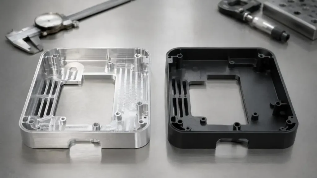
A polished surface may begin with approximately 0.5–1° of draft, while deeper textures normally require more. CNC machining can produce the intended shape without proving that a textured molded wall will release cleanly.
Ra values also do not define the complete visual result. Gloss, texture replication, flow lines, weld lines, color distribution, and gate blush require molded samples.
Snap-Fits and Living Hinges
CNC machining may leave tool radii, cut through the material's original orientation, or require a modified hinge geometry. If the feature depends on molecular orientation, repeated flexing, or controlled strain, testing should move to production-intent resin and injection molding before DVT approval.
LKK incorporates wall-thickness review, draft analysis, gate placement, weld-line prediction, snap-fit validation, undercut strategy, and moldability assessment into its DFM workflow. These checks connect prototype results to the intended manufacturing process instead of treating the sample as an isolated model.
Comparing Four Practical Prototype Routes
| Route | Appropriate Use | Evidence Limitation |
| CNC machining | Early fit, ergonomics, machining-grade functional tests | Does not reproduce molding defects |
| Vacuum casting | Cosmetic batches and user trials | ABS-like or PC-like polyurethane is not production resin |
| Aluminum rapid tooling | Production-resin samples with faster tooling changes | Cooling and tool wear may differ from final steel tooling |
| Production-intent steel tooling | DVT/PVT, process capability and pilot production | Higher initial cost and expensive late revisions |
LKK Prototyping and Rapid Tooling Capabilities
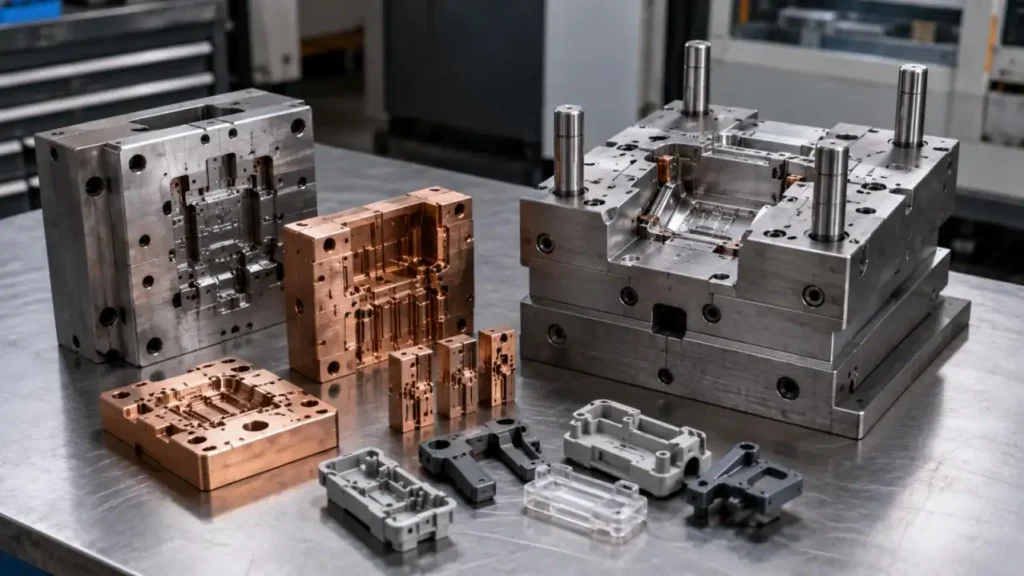
LKK combines CNC machining, SLA/SLS/MJF printing, vacuum casting, and rapid tooling to match different validation stages.
| Process | Technical Capability | Suitable Evidence |
| CNC Prototyping | ABS, POM, aluminum and stainless steel; ±0.05 mm; Ra ≤0.8 μm | Fit, assembly and functional testing |
| Vacuum Casting | Approximately 50–200 pieces | Cosmetic models and low-volume user trials |
| Rapid Tooling | Approximately 50–500 pieces | Production-resin and molded-feature validation |
| Mold/Cavity CNC | Critical mating surfaces ±0.005 mm; finished cavities Ra ≤0.4 μm | Dimensional stability and tooling accuracy |
| EDM & Wire EDM | Mirror EDM Ra ≤0.1 μm; wire-cut accuracy ±0.003 mm | Deep slots, narrow gaps, textures and inserts |
Key tooling controls include:
•Mold engineering: 3D parting design, DME/HASCO mold-base selection, conformal cooling optimization and FEA verification.
•Inspection: CMM accuracy of ±0.002 mm, white-light surface measurement and spectrometer-based alloy verification.
•Assembly validation: Core-to-cavity gap ≤0.01 mm, ejection resistance ≤5 N and cooling-pressure testing at 0.5 MPa for 30 minutes.
•Trial molding: 50–3,000-ton presses, process variation targets ≤2% and dimensional capability targets up to Cpk ≥1.67.
Final quantity, tolerance and lead time still depend on geometry, resin, finish, cavity layout and inspection requirements.
Match the Prototype Route to the Development Gate
Concept and EVT: Remove Geometric Uncertainty
CNC is normally effective for verifying:
•PCB, connector and battery clearances
•Fastener access and assembly sequence
•Ergonomics and enclosure proportions
•Early sealing layouts
•Critical tolerance-stack assumptions
Both worst-case and root-sum-square tolerance analyses should be completed before interpreting a successful hand-built assembly.
DVT: Test Process-Dependent Functions
Injection-molded prototypes become important when testing:
•Snap-fits, hinges and press fits
•Drop, impact, chemical and thermal resistance
•IP sealing after molded distortion
•Cosmetic surfaces and color consistency
•Inserts, ultrasonic welding and adhesive bonding
PVT: Confirm the Production System
PVT parts should represent the planned tool steel, cavity count, runner, gate, cooling circuit, resin, colorant and molding window. A single acceptable first article does not establish process capability.
A Cpk of 1.33 is a common production reference, while critical applications may specify 1.67. However, Cpk is meaningful only after the process is stable, the measurement system is suitable, and enough representative data have been collected. It should not be inferred from a few carefully selected prototypes.
Include Assembly, Tool Maintenance and Conditioning
Prototype reports should record more than dimensions. Heat-set inserts, screw torque, welding energy, adhesive cure, gasket compression and coating thickness can change functional results.
Mold revisions and maintenance also require traceability. Insert replacement, vent cleaning, polishing, gate adjustment, and cooling-system work can alter later samples. LKK connects prototype fabrication with assembly workflow testing, engineering change notice tracking, first article inspection planning, and tooling lifecycle management.
Verify Standards Before Accepting the Result
Injection-molded dimensions may be evaluated under ISO 20457:2026, but that standard does not define acceptance for sink marks, flow structures, roughness, or joint lines. Relevant validation may also include:
•ISO 294-4 for molding and post-molding shrinkage
•ISO 527-2:2025 or ASTM D638 for tensile testing
•ISO 21920 for surface-texture specification
•UL 94 verification for the exact grade, color and thickness
•Material COA, conditioning records and molding parameters
•Make the Procurement Decision on Total Validation Cost
The cost comparison should be calculated as:
CCNC = Csetup + N(Cmachining +Cfinishing +Cinspection)
Cmolding=Ctool + Ctrial +N(Cpart)+ Cinspection + Ctool changes
There is no universal break-even quantity. The design revision probability, required evidence, resin availability, tool configuration and inspection plan must be included.
The strong CNC prototype vs. injection-molded prototype strategy is often sequential: use CNC to resolve geometry quickly, then use injection-molded samples to verify molding-dependent risks. LKK's integrated DFM, CNC, rapid tooling, mold-trial and inspection capabilities can help teams define that transition before costly production tooling is released.
FAQs
Q1. Does LKK provide both CNC and injection-molded prototypes?
Yes. LKK does CNC prototype machining, rapid tooling, molded parts, as well as injection molds. It also provides SLA, SLS, MJF, and vacuum casting if intermediate validation methods are needed.
Q2. What CNC prototype accuracy can LKK achieve?
LKK's CNC prototype accuracy is in the range of ±0.05 mm and Ra ≤0.8 μm for support geometries and materials. Actual tolerance is impacted by the dimensions of the part, the type of material, the thickness of the walls, the datum strategy, and how accessible the features of the part are.
Q3. When does LKK recommend using a CNC prototype?
CNC is used for early fit checks, ergonomic evaluations, enclosure assembly, connector placement, fastener access, sealing layout reviews, and preliminary functional testing.
Q4. When is an injection-molded prototype needed?
Injection-molded prototypes are typically needed when LKK needs to evaluate the effects of sink marks, weld lines and textured surface filling of glass fibers, molds, gate effects, and the performance of the production resin.
Q5. Is it possible to manufacture a CNC prototype that uses the same plastic as the production part?
Yes, if the required grade is available as machinable sheet, block, rod, etc.
Contact Us



- 20+ Design Industries Serviced
- 200+ Product Categories
- 1,000+ Industry Leaders Served
- 10,000+ Products Successfully Launched

Founder and Chairman of LKK Design Group
Ready to get started? Connect with us today!
 Talk to Our Team